Article Number: 000121656
How to set up and manage LLDP (Link Layer Discovery Protocol) on Dell Networking X Series switches.
Summary: Setting up and manage LLDP (Link Layer Discovery Protocol) on Dell EMC Networking X-Series switches.
Article Content
Instructions
Article description: This article explains how to set up and manage LLDP (Link Layer Discovery Protocol) on Dell Networking X Series switches.
Objectives
- Overview
- LLDP Properties
- LLDP Port Settings
- Neighboring Switch Information
LLDP enables network managers to troubleshoot and enhance network management by discovering and maintaining network topologies over multivendor environments. LLDP discovers network neighbors by standardizing methods for network devices to advertise themselves to other systems, and to store discovered information. Discovery information includes:
- Device identification
- Device capabilities
- Device configuration
A device advertises itself in LLDP messages. Information in the messages is in Type Length Value (TLV) format. LLDP devices must support chassis and port ID TLVs, as well as system name, system ID, system description, and system capability TLVs.
LLDP Media Endpoint Discovery (LLDP-MED) increases network flexibility by enabling various IP systems to co-exist on a single network, and provides the following features:
- Detailed network topology information, including information on which devices are located on the network and where the devices are located, for example, which IP phone is connect to which port, which software is running on which switch, and which port is connected to which device.
- Automatic deployment of policies over networks for:
– QoS Policies
– Voice VLANs
- Emergency Call Service (E-911) via IP phone location information.
- Troubleshooting information. LLDP MED sends network managers alerts for:
– Port speed and duplex mode conflicts
– QoS policy misconfigurations
LLDP Properties
To enable and configure LLDP:
1 Click Network Administration > Link Layer Discovery Protocol (LLDP)> LLDP Properties.
The current LLDP properties are displayed.

Note: Under normal circumstances all you would modify the status on this page, the "enabled" "disabled" option. Please consult a Dell Networking agent before changing the default timers.
2 Click Edit and enter the fields:
– LLDP Status — Enable/disable LLDP on the device.
– Updates Interval (Sec) — Enter the rate at which LLDP advertisement updates are sent.
– Reinitializing Delay (Sec) — Enter the minimum time, in seconds, that an LLDP port waits before reinitializing LLDP transmission.
– Hold Multiplier (Sec) — Enter the hold time to be sent in the LLDP update packets, as a multiple of the timer value.
– Transmit Delay (Sec) — Enter the amount of time that passes between successive LLDP frame transmissions, due to changes in the LLDP local systems MIB.
To use the default values for any field, select Use Default.
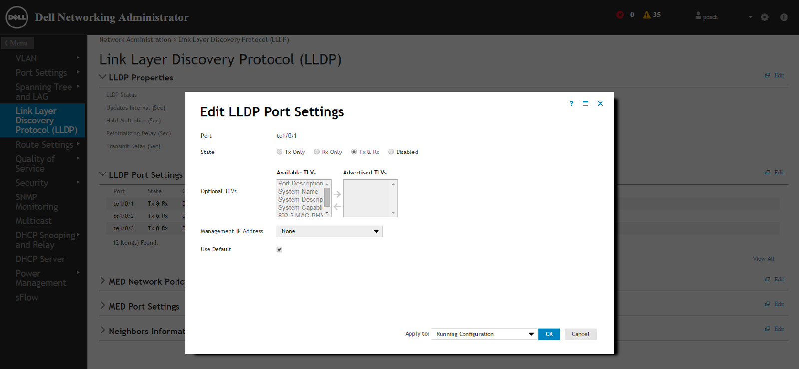
LLDP Port Settings
You can set send receive status on the port level, optional TLV advertisements. Below are the steps to configure the options available.
1 Click Network Administration > Link Layer Discovery Protocol (LLDP)> LLDP Port Settings.
LLDP settings for all ports are displayed.
Note: Unless otherwise instructed by Dell Networking agent leave the advanced LLDP port settings as default.
2 Click Edit and click the Edit icon of the individual port to be configured.
3 Select the transmission type on which LLDP is to be configured in the State field. The possible options are:
3 Select the transmission type on which LLDP is to be configured in the State field. The possible options are:
– Tx Only — Enables LLDP on transmitting LLDP packets only.
– Rx Only — Enables LLDP on receiving LLDP packets only.
– Tx & Rx — Enables LLDP on transmitting and receiving LLDP packets.
– Disabled — LLDP is disabled on the port.
4 Move the optional TLVs that the switch should advertise from the Available TLV list to the Optional TLV list. The TLVs advertise the following:
– Port Description — Information about the port, including manufacturer, product name, and hardware/software version.
– System Name — System's assigned name (in alpha-numeric format). This value equals the sysName object.
– System Description — Description of the network entity (in alphanumeric format). This includes the system's name and versions of the hardware, operating system, and networking software supported by the switch. This value equals the sysDescr object.
– System Capabilities — Primary functions of the switch, and whether or not these functions are enabled in the switch. The capabilities are indicated by two octets. Bits 0 through 7 indicate Other, Repeater, Bridge, WLAN AP, Router, Telephone, DOCSIS cable device, and station respectively. Bits 8 through 15 are reserved.
– 802.3 MAC-PHY — Duplex and bit rate capability and the current duplex and bit rate settings of the sending device. It also advertises whether the current settings are due to auto-negotiation or manual configuration.
An alternative way to select the TLVs is to select the Use Default field, in which case only mandatory TLVs are used. These are: Chassis subtype (MAC address), Port subtype (port number), and TTL (time-to-leave).
5 Enter the Management IP Address that is advertised from the interface.
Check Use Default to use the default Management IP address.
Neighboring Switch Information
You can view connecting devices that are sending LLDP packets from this location. It is helpful with initial connectivity on trouble shooting what devices are physically connected to specific ports on the X Series switch.
To view neighbors information:
1 Click Network Administration > Link Layer Discovery Protocol (LLDP) > Neighbors Information.
The following fields are displayed for each port on the device that has a discovered neighbor:
– Port — Port number for which neighboring information is displayed
– Device ID — Neighboring device ID
– System Name — Name of the neighboring system
– Port ID — Neighboring port ID
– Capabilities — Neighboring device capabilities
2 Click Clear Neighbors Table to delete all the entries or select Remove to delete a specific port entry.
You can clear or remove to insure that the entry comes back and is a valid current connection.
Article Properties
Affected Product
Dell Networking X1000 Series, Dell Networking X4000 Series
Last Published Date
21 Feb 2021
Version
3
Article Type
How To